Start With One Observable Goal
A first microcontroller project becomes manageable when its result can be stated in one sentence: read a temperature sensor once per second and turn on an LED above a threshold. That sentence identifies an input, an output, a timing expectation, and a behavior you can test. “Build a smart home device” does not. Keep wireless connectivity, displays, batteries, and mobile apps outside the first milestone unless one of them is the core lesson.
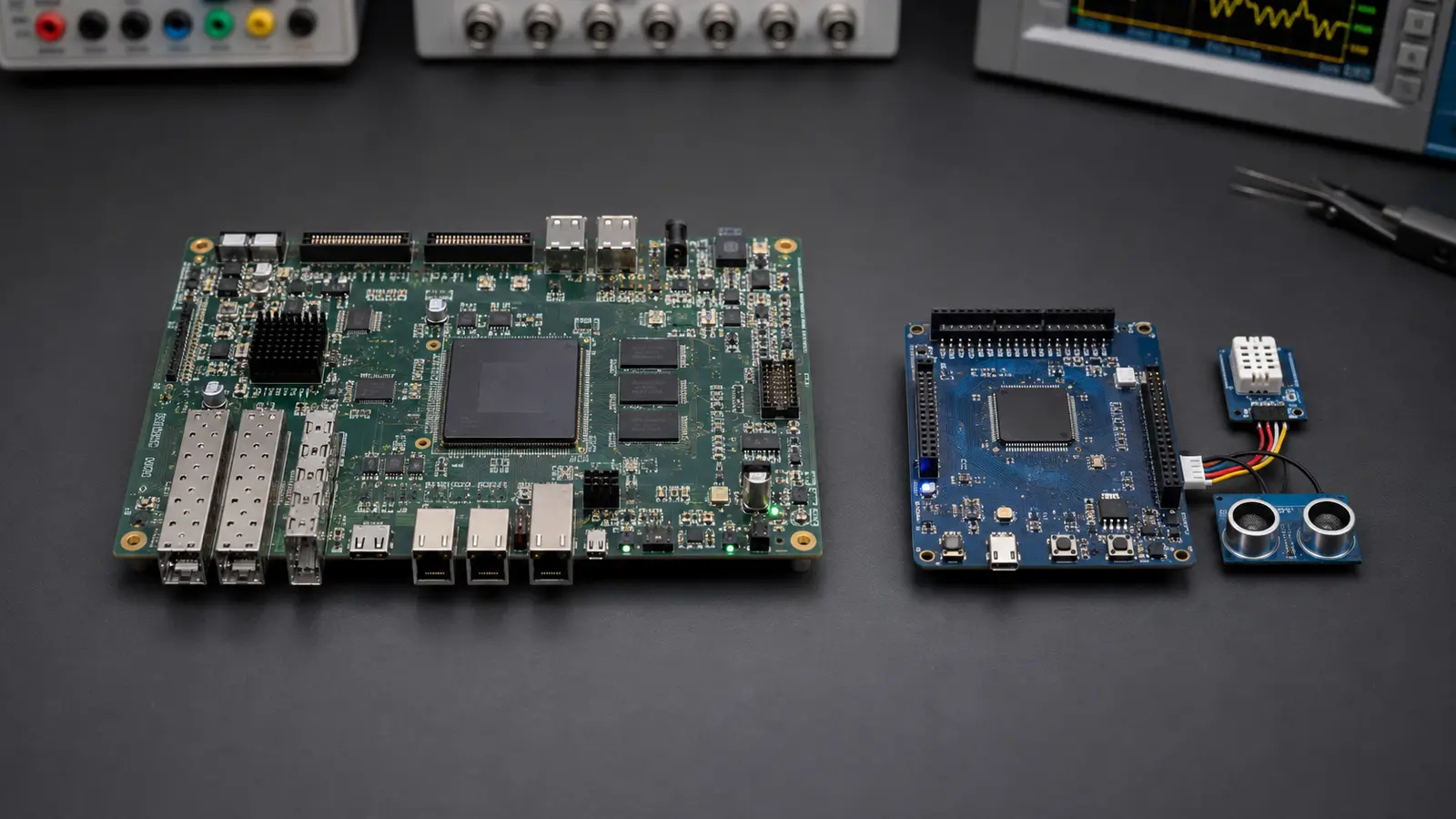
Choose a development board with documentation, a debugger or serial connection, and enough accessible pins for the sensor. Then read the board guide and the sensor data sheet before wiring anything. Confirm the logic voltage, supply range, connector pinout, and whether the input or output needs a pull-up resistor. The board label may be convenient, but the electrical limits in its documentation are the authority.
Draw The System Before Connecting Wires
A small block diagram prevents many mistakes. Draw the power source, microcontroller, sensor, output, and communication link. Mark the voltage beside each block and show which device provides power. This simple picture exposes conflicts such as a 5-volt output feeding a 3.3-volt input, two modules trying to drive the same line, or a sensor whose current demand exceeds a board regulator.
Next, create a pin map in your notes. Record the board pin name, microcontroller function, connected device, direction, and expected idle state. Distinguish physical connector labels from the processor's internal pin names. Keeping this map beside the firmware eliminates the recurring question of whether a failure is in code or wiring.
Keep The First Circuit Boring
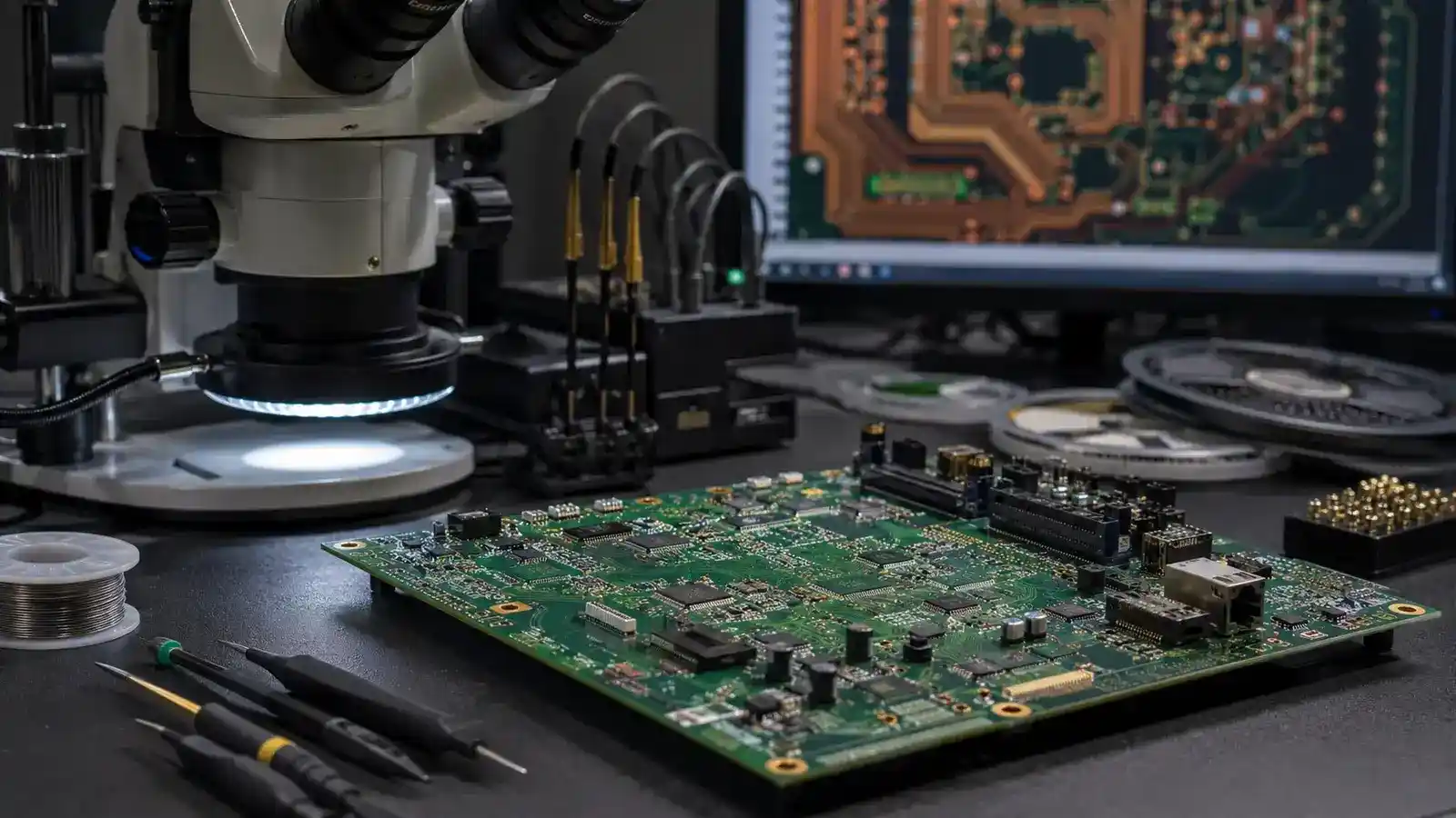
Use short wires, a shared ground, and one peripheral at a time. Add decoupling recommended by the device manufacturer and avoid powering motors, relays, or bright LED strips directly from a general-purpose pin. Loads that draw meaningful current need an appropriate driver and power path. If the final product requires a custom board, learn with the development board first and move to a disciplined PCB design workflow only after the circuit behavior is understood.
Bring The Project Up In Stages
- Verify the toolchain. Build and load a minimal example supplied for the board.
- Prove one output. Blink an LED or toggle a test pin at a slow, visible rate.
- Prove communication. Send a fixed serial message before printing live sensor data.
- Read the sensor identity or a stable value. Compare the result with the data sheet.
- Add the decision rule. Apply the threshold only after the input is trustworthy.
Save a working version after every stage. When the next change fails, return to the last known-good build and compare one difference. This is faster than rewriting several modules at once. It also creates evidence about the actual fault instead of encouraging random component swaps.
Measure Before Guessing
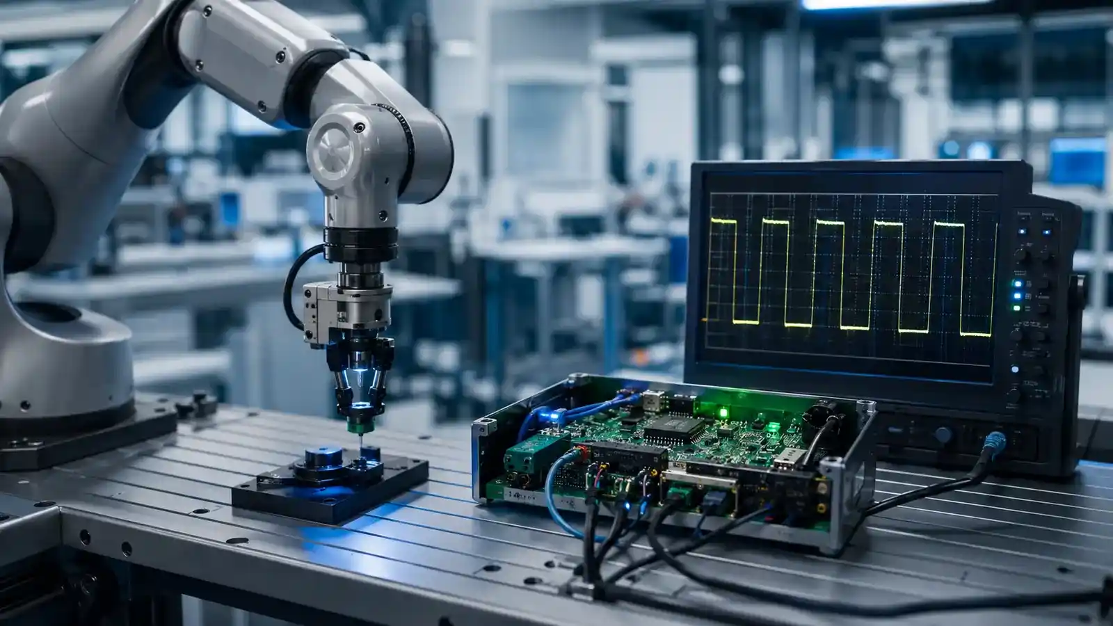
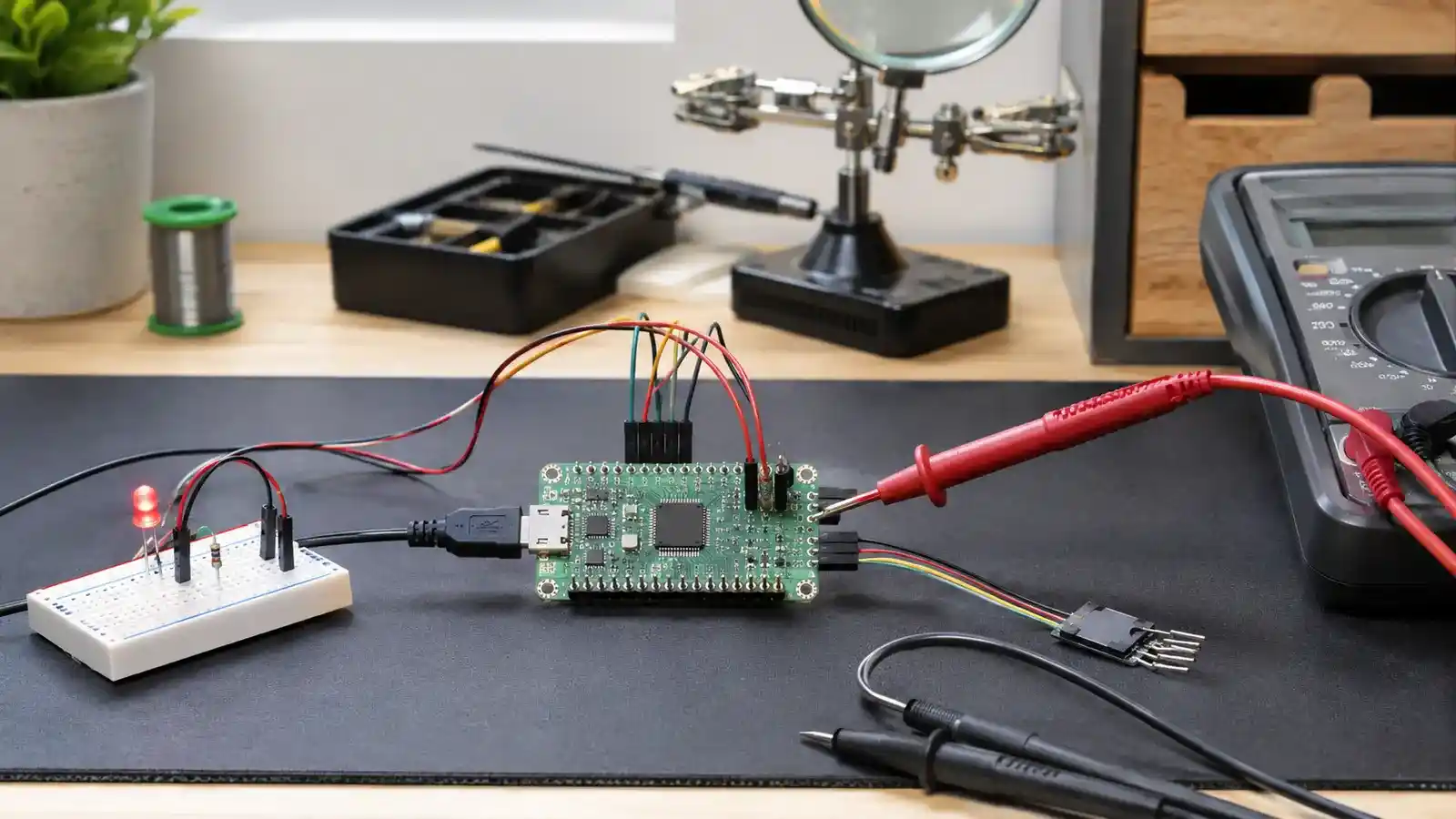
A multimeter can confirm supply voltage, continuity, and static logic levels. A logic analyzer reveals whether digital messages are present and correctly timed. An oscilloscope is useful when signal shape, noise, rise time, or power integrity matters. Serial logging can show program state, but excessive logging changes timing and may hide faults, especially when the application grows toward real-time deadlines.
When a sensor reports nonsense, check power and ground first, then confirm pin direction and interface settings. For I2C, verify the address and pull-ups. For SPI, verify clock polarity, phase, chip-select behavior, and voltage levels. For analog input, measure the signal at the pin and compare it with the converter reference. Treat every reading as a clue tied to a testable hypothesis.
| Symptom | First evidence to collect | Likely area |
|---|---|---|
| Board resets when output turns on | Supply voltage during the event | Power path or load current |
| Sensor never responds | Bus activity and device address | Wiring or interface setup |
| Values jump randomly | Ground, reference, and raw readings | Noise or conversion setup |
| Behavior changes with logging | Timing with and without messages | Blocking code or missed deadline |
Turn A Demo Into A Repeatable Prototype
Once the main behavior works, test the edges. Disconnect and reconnect the sensor. Cycle power repeatedly. Try values just above and below the threshold. Define what the output should do when data is missing. Replace long blocking delays with state-based timing so the system can keep reading inputs while it waits. If several tasks must meet bounded timing, the scheduling ideas in the real-time guide become important.
Connected prototypes need another layer of decisions. Decide what happens when the network is unavailable, how readings are buffered, and whether a failed upload can block the local control function. The guide to reliable IoT sensor networks expands that system boundary from one board to an entire fleet.
Finally, record the firmware version, wiring revision, test conditions, and known limitations. A prototype becomes useful engineering when another person can reproduce its behavior. That record also makes it easier to decide whether the next version still belongs on a microcontroller or whether parallel logic suggests an FPGA comparison.
Common First-Project Questions
Should I Start With Assembly Or C?
Start with the supported language and examples for the board, which is commonly C or C++. Learn registers and low-level behavior as the project requires them. Assembly is valuable for architecture study and specialized optimization, but it is not a prerequisite for proving a sensor-to-output design.
Do I Need Expensive Test Equipment?
No. A basic multimeter, careful documentation, and a board with serial output can solve many first-project problems. Add a logic analyzer or oscilloscope when the evidence you need involves timing or signal quality.
When Is A Breadboard No Longer Enough?
Move beyond it when connections become unreliable, current or frequency rises, the physical arrangement affects performance, or the design must be reproduced. At that point, a schematic and PCB are part of the experiment rather than cosmetic finishing.